
I have a new website and blog. If you want to continue following my adventures in the world of CG and tshirt designing, please bookmark the new address.
Thanks for reading this blog. Ill see you at the new site!
I have a new website and blog. If you want to continue following my adventures in the world of CG and tshirt designing, please bookmark the new address.
Thanks for reading this blog. Ill see you at the new site!
Im not sure I can truely put into words how frustrating creating the IK leg for this rig was. I do know, however, that creating a stretchy IK leg should not take almost 48 hours to get working.
Before I duplicated my bones, I decided I wanted to put some extra bones along the lower leg to enable smoother twisting. To ensure things worked nicely later on I wanted to ensure that the three new bones I inserted were exactly a quarter, half and three-quarters of the way along the calf. To do this, I parent constrained each of the three bones to both the knee and the ankle, and made sure maintain offset was unticked. This placed all three bones exactly half way between the knee and ankle. I then changed the weighting of the parenting to two of them. Femur01 was weighted 0.75 to the knee and 0.25 to the ankle, whilst Femur03 was weighted 0.25 to the knee and 0.75 to the ankle. I then deleted the constraints and used comet tools to orient the joints correctly.
Once this was complete I created two duplicates (one for IK, one for FK). I then created a third duplicate in which I deleted the three femur joints and reparented the ankle straight to the knee. This was so that I had just two bones in the IK system. I called it the IKGuide. I created an IK on the joints and made a simple cube controller for the foot. I parented the IK handle to this control. I then orient constrained the ankle bone to this controller so that it would not rotate as the leg moved. Finally, I created a simple circle controller and parent constrained the hip bone at the top of the IK to the circle.

With the IK built and working, I started to set up the IK stretch. Like the IK spine, I needed to know how long the leg was at any one point in time. However, I only needed the straight line distance from hip to ankle. I used the distance tool for this. I aligned one locator with the hip and one with the ankle and then parented them to the corresponding controllers. Now, as the leg moved, the distance tool would always give the distance from hip to ankle. At this point I also realised I had not created a knee controller. For this I used an arrow shape. I point constrained the arrow to both the hip and ankle (with maintain offset unticked). This placed the arrow on the plane between the two, directly in the centre. I then used an aim constraint to ensure the arrow was pointing directly at the knee. After deleting both constraints I moved the arrow in front of the knee and set up a pole vector constraint on the IK.

To wire up the stretchy leg I used another multiply divide node and, like the spine, the distance was wired to the first input. The second input needed to be the length of the thigh bone plus the length of the calf bone. As the joints had been oriented correctly this could be found simply by adding the x transform of the knee and ankle together. I changed the node to divide and wired the output to the “true” output of a condition node. The “false” output was left as 1. The condition node also had the distance in the first input and the length of the two bones as the second. It then compared the two lengths, and if the distance was greater than the bone length, the condition was true. I then wired this condition node to the x scale (length) of the thigh and calf. The two bones of the IK scaled nicely. Unfortunately, the ankle and foot bones were being scaled strangely when the leg stretched, despite not being wired to the condition node. I even checked the scale of both and x, y and z were all still showing as 1. This meant the bones shouldnt have been scaling at all.


I tried deleting the IK and remaking it, but the problem persisted. I then tried moving the controls with no IK present at all, and the ankle and foot continued stretching strangely. I could only assume there was something strange with the bones, so I deleted the IKGuide joints and re-created them. I set everything back up, re-wired the thigh and calf x-scale to the condition node and tested it again. I had exactly the same problem all over again. I tried re-creating the bones once more that evening but with no success. I finally decided the only option was to go to bed and look at it with a fresh mind in the morning.
As is often the way with re-visiting a problem the next day, I tracked the issue down quite quickly. I had all the joints in the hypershade to make sure my ankle and foot definitely hadnt managed to end up wired to anything and I realised there was no line showing the parenting of ankle to knee. I un-parented the ankle bone and re-parented it to the knee and the problem disappeared. I was delighted, until I found yet another problem. Whilst the ankle was no longer scaling strangely, it still was not doing what I expected when I moved the hip too far away. Despite being orient constrained the foot controller (and as such theoretically unable to rotate by itself) when I moved the hip controller forwards or backwards so that the leg stretched, my ankle would rotate.


I decided to fix the problem by simply creating a new version of the ankle and foot bone. I simply point constrained the new ankle joint to the one on the IK leg and orient constrained it to the controller again. Success! Problem solved, just not as tidily as I would have liked. It also left me feeling frustrated because I wanted to know why the problem had occured so I could avoid it in the future. Still, at least the problem was gone and I could get on with parent constraining the IK joints to the IKGuide joints. I unticked maintain offset and parent constrained all the joints to their respective guide joints. I parented the three femur joints in the same way I created them; by parenting to both knee and ankle and then editting the weights. However, what I hadn’t thought of was that a parent constraint would cause the joints to rotate out of alignment due to the ankle’s orientation. I pondered the problem for a while and decided I would simply ensure to maintain offsets when constraining the deform joints to the IK joints.

I then set to work creating a control system for the toes so that I could create a simple set of foot roll controllers. Initially I decided to place a circle controller around each joint of the toes, but it quickly became clear that some of them would be hard to select.

Instead, I moved the curve shapes of the controllers above each toe joint and this made them much clearer and easier to see. Finally, I also made a main controller that would be used to curl all the joints of a toe. I then began creating a simple set of foot roll controls and with some re-parenting of the IK handle my IK leg was complete.


Unfortunately, I quickly checked things in my orthographic side view and realised that at some point during the creation process I had managed to cause the entire IK system to move out of alignment from its starting position, despite all the controls being at 0, 0, 0.

The only option was to yet again build the entire IK leg. I deleted all my bones, mirrored the right hand leg to the left hand side. The good thing was, that at least this time all the controllers were already built so all I needed to do was wire everything up correctly, and make sure my controllers were correctly aligned before constraining/parenting things to them. Fortunately, this time I got it right and my left IK leg was finally complete. Hooray!
I finally got the mesh back yesterday, and Im happy to say its actually symmetrical this time.

As such, I’ve been able to get cracking with building the control system for the toony rig. I started with the spine as I feel its such a central part of the control system, and almost everything else is parented to it in some way. My first step was to duplicate the bones that I want to apply the IK spine to. This means if I made any mistakes, moved anything by accident, I wouldn’t ruin the position/orientation etc. of the deform skeleton and I could easily delete the duplicate and start again. I tend to insert IK (or whatever is appropriate) to the name of the joint to differentiate it from the deform skeleton.
Once I’ve got my duplicate I hid the deform skeleton so that I couldn’t affect it or move it whilst working on the controls. I applied an IK spline with two spans to the spine. This means that there are control points for each end, as well as a single control point in the center to affect the curve. I created a cluster for each of the control points. These control the shape of the curve and the shape of the curve drives the position of the bones.

I then needed to build the actual controllers for the spine. Comet tools provides a quick way to make a bunch of spline shapes, but they are all quite simple, sharp edged splines. They never look particularly nice, and they don’t fit the shape of the body all that well. As such, I like to make a lot of my controllers by hand. To do this, I used the mesh itself to guide the shapes. I turned on snap to vertex and created a selection of curves that flowed around the area of the body that I wanted to control. I generally tweak them slightly afterwards to make sure the ends of the curves meet up and dont leave gaps anywhere. With this complete, I had a bunch of individual curves that could be selected seperately. What I actually want is to be able to click anywhere on any of the curves and to have them all selected. To do this, I had to reparent the individual “curveshapes” to a single curve. This can be easily done by selecting the “curveshape”, then shift selecting the curve I want to parent it to. I then simply use a single line of MEL script: “parent -r -s”. This leaves an empty curve node with no shape that can be deleted.


Once all my controllers were built I aligned them with the correct bones and parented the clusters to each controller. I also created two groups for each controller to be parented within. One I suffix with _SDK and one with _0. The _0 is my null group. The 0 point so that I do not need to use freeze transformations. The _SDK group allows me to set up parent constraints for a controller, whilst still giving the animator the ability to animate it. For the spine, I parent constrained the middle controller _SDK to both the top and bottom spine controllers. This means that the middle controller will always remain halfway between the top and bottom of the spine.
Once this was complete I decided to test the spine to check it was working correctly. Unfortunately, it wasn’t. I hadn’t realised I had only given the IK spline four bones to move around. When the curve had extreme bends the bones just averaged out their positions and the shape of the curve was lost. This meant rebuilding the deform spine with more bones so that there were enough joints to follow the spline curve more accurately. Having added them, I made sure to tidy up their orientation with comet tools again.

I then repeated the process of applying an IK spline to the duplicate set of bones and creating clusters for the three control points of the curve. I re-positioned the controllers to ensure they were correctly aligned with the new bones and then parented the clusters to the controls. I also set the twist controls for the IK spline to make the hip and chest controllers control
the spine rotation.

Finally, I wanted my spine to be stretchy as this is meant to be a “cartoony” rig. I created a multiplydivide node which I set to divide. I also created an arc length info node for the spline curve. This provided me with the length of the curve at any time. I wired the length into the first input of the divide node and put the length of the curve when all controls were at 0, 0, 0 into the second input of the divide. This means that the output will be the current length of the spine divided by the original length. I then simply wired the output into the scale x (the length) of all the joints in the spine.

Success! An easy to use stretchy IK spine.
With my scenes set up for my animators on the elephant project, I can finally get to work on my side project; the toony rig. The first step to rigging anything is to build the joints that will drive the deformation of the mesh. I call this the deform skeleton.
The first thing I create is always the spine. The pelvis is the start of the chain and the head the end. I generally name joints as I go to avoid confusion when the entire skeleton has been built. I used the same naming convention as my elephant rig. A prefix of C_, L_ or R_, the name of the joint and a suffix of _jnt.


The arm was the next thing I built. I initially place the bones using the orthographic front view. I line up the joint positions to the hand as well as possible. However, because my view is orthographic, the joints are all created on a flat plane. This does not match the shape of the hand, so I then use the perspective view to line everything up correctly. I then repeat the process with the foot, but this time I create the joints from the orthographic side view. To ensure my joints orient correctly later on, I make sure that the first finger or toe I create is the most central one. This simply means that the joint in the palm or sole of the foot will point to this finger when oriented, instead of out to one side at, for example, the thumb or little toe.


With all the joints created on one side of the body, I now need to correctly orient the joints. This is good practice because it ensures the joints will all rotate nicely in the same axis. These two images show the spine axes before and after the orientation. I use comet tools to do the joint orientation.


After orienting the joints on the hands and foot, I tweaked the angles of the thumb. The reason for this is so that if all the finger joints are selected and rotated in one axis, they should close to form a fist. This makes it much easier for the animator to work and keeps the animation curves much cleaner.


With the orientations tidied I could finally mirror my arms and legs so that I had a complete skeleton. Unfortunately, once I had mirrored the joints, it was clear that the mesh had not been mirrored correctly and was not symmetrical. I have contacted the artist and asked if they can have a look and fix it. However, since it is the easter holidays, I have no idea when they will see my email, let alone send me the fixed mesh. I dont want to continue rigging, just in case there is a problem and they are unable to get things symmetrical for me, as that would mean rebuilding the joints for the right arm/leg seperately and I would have to redo any work I had already done.

I think the camera tracking has been one of my biggest worries during this project. It is something I have only fleeting experience with, but it is essential for producing a polished end product. When filming any moving camera shots we decided to keep them on a tripod and just pan to keep things simpler. The first shot I chose to track was probably one of the most important shots in the entire project: the very final shot where the elephant gives the monkey back to the mother.
I have been using Boujou as this was the program we were introduced to during a previous compositing project earlier in the year. It had produced a great result for me in the past, but I was aware that others on my course were not so fortunate. Boujou does not always get it right first time. I imported the footage and set Boujou to tracking the movement in the image. To do this, Boujou latches onto distinctive areas in the image (ie colour changes which suggest edges of objects). It then tracks how these points move throughout the footage. To get the best result, it is generally necessary to have points that occur on the x, y and z axis within the 3d space of the shot. However the shot I was working with had a flat wall in the background (which meant no track points in the z axis) and I worried that Boujou would struggle to know how close or far away the camera was throughout the shot. The next stage of the camera tracking was to ask Boujou to use these track points and their movement to create a camera in 3d space that matches the movement of the camera in the shot. Thankfully I found an option at this point to tell Boujou that the camera was nodal. This means Boujou knew that the camera was on a tripod and in a fixed position and could only rotate. Finally, I could export the information into Maya and check to see whether it worked. To my delight, the tracking seemed great. However, I quickly noticed that objects in the scene seemed to suddenly move up and down, or side to side out of time with the footage. Since I have no knowledge of how to correct this in Boujou I decided to see if I could fix it without too much effort in Maya. I played the animation until I found a moment when objects in the scene moved out of sync with the footage. I then checked the camera’s curves in the graph editor to check if there were any odd kinks or jumps. Most of the problems were extremely easy to find and fix, but there was one that was extremely frustrating. About two thirds of the way through the scene skipped sideways suddenly and then gently eased back into its original position. I could find nothing on any of the curves that would indicate the camera was rotating like this. I spent a long time trying to establish whether it was just one curve or all of them effecting it, but eventually, after some painstaking work tweaking each individual key, I managed to tidy it up so that the movement was barely noticeable.
I wanted to set up the scenes that my animators would be using before I did anything else, so I then moved on to some of the scenes with a fixed camera. I created a new Maya file for each one, referenced the elephant rig and created a new camera. I created an image plane for the camera with the .png sequence of the correct shot. I cannot believe how difficult it was to then actually manage to position the camera in 3d space so that it lined up with the footage. I had foolishly assumed that it would be the moving camera shots that would cause me the issues when all along it was positioning cameras by hand that would be my downfall. The situation was made more frustrating by the knowledge that I had assumed Motion Graphics were taught easy ways to work out the position of cameras in still shots. In 2nd year, we learnt to take a photo with the camera in the same position and an item in the shot that you knew the dimensions of. You could then use this item to help line up the camera. Since I was relying on the knowledge of my Motion Graphics students as I knew they had plenty more experience than me, I readily accepted their answer when they assured me nothing was needed for these shots. It was pretty galling when I asked them later on how I would be positioning the cameras and they answered “by eye”. I have at least learnt one lesson from this. Whenever possible, if filming for a VFX composition with a still camera, make sure there is something in shot that you know the exact dimensions of. It will make your life so much easier.
Now that I have all the footage from both shoots, I’ve finally been able to sit down and start sorting through which shots worked best. I created a new Premiere file and set to work putting it all together. Its quite exciting to see it coming together, and Im surprised at how long the video is. I sat down with a tutor to discuss timings as I was worried that some things felt a bit slow. However I wasn’t certain if this was just because the scenes were currently missing a CG elephant. He agreed with me though and so I started being a bit more harsh on the footage, cutting out unnecessary seconds at the beginning and ends of shots.
This is the final result:
So yesterday, I finally got the elephant rig to a point where it could be referenced into the animator’s files. One of the major things I worked on was updating all of the controllers so that they are clearer and fit the model nicely. I foolishly assumed this would be easy, but I hadn’t reckoned on the awkwardness of the curve creation tools in Maya. It took me quite a while of just repeatedly trying to create shapes and deleting them as they failed to work. I think my determination to create things that were perfectly symmetrical possibly did not help the situation, but an assymetrical controller just doesn’t look as neat and clean in my opinion. Eventually I hit upon the idea of using the snap to vertex tool and using the edges and vertices of the elephant to help me create controllers that fit nicely to the contours of the elephants body. Having drawn a selection of curves I needed to then join all the individual curves together into a single item. This involved reparenting the individual curve shapes a single curve node and then deleting the rest of the empty nodes. Frustratingly I could find no way to tell Maya to actually combine all the shapes nodes on each curve into one single curve, but each controller selects the entire item wherever you click it, so it still works, its just not as clean as I would like it to be. I then scaled the controllers out from the body slightly and coloured them. I had hoped I could then parent these new shapes to the controllers already in existence (as I had with each individual curve to make the new controller), but every time I tried, the new controllers were rotated strangely and moved away from the body. This was due to the difference in positions of the pivots of the old and new controllers. Hoping I could avoid having to reposition each new controller I decided to instead break all the constraints and set everything back up on the new controllers. It turns out I still had to reposition the pivots, and so rearrange the shapes, but at least I knew I didnt have to spend time trying to delete the shapes of the old controllers, I could just remove the entire item.
I did, however, forget to redirect the spine rotation to the new controllers, so I had a bit of a scare later in the evening when I created a global control and tried to check that everything moved as I wanted it to. When the elephant rotated 90 degrees, the spine flipped, presenting a problem I had first encountered in my 2nd year when rigging a quadroped in 3ds Max. I panicked for a while that my IK spline spine was in fact broken and I would have to come up with a completely new set up. However after I checked the IK I realised that in creating the new controllers, I had not told it to use them to decide the rotation of the spine. Thankfully, this fixed the problem.

I also needed to update the rig with the new low poly model that Paul had altered for me. I brought the mesh in and whilst trying to work out how to load the skinning from the old mesh to the new mesh, I found an option that instead replaced an old mesh with a new mesh. I tried it out and it worked brilliantly. The old mesh changed to the new mesh. However, I now had two versions of the new mesh, one that was skinned, and one that was not. Assuming that the unskinned mesh was no longer needed I promptly deleted it. A couple of hours later, when testing some other part of the rig, I discovered my mesh no longer seemed to be moving with the bones. Confused I saved the file under a new name, closed it and reopened it. To my horror, the mesh was now invisible. The outliner still showed all the various parts of the mesh, but I couldn’t get them to appear.

I hastily opened my previous iteration only to discover that that file suddenly had exactly the same problem. Desperately hoping I hadn’t somehow broken every single version (and so lost all my skinning) I tried the next step back. To my relief the old mesh was there and skinned and working absolutely fine. I had simply lost my day’s rigging work, but nothing else. Deciding that replacing the mesh clearly wasn’t the best method to update my rig, I started working on saving off the skinning so that I could load it onto the new mesh. Frustratingly it seemed Maya was only giving me the option to load each bones skinning one at a time. It was doable, but a bit pointlessly time consuming. Fortunately, I knew one of my classmates, Joe, had successfully, and easily, loaded skinning onto new meshes during his project. I asked him about it and he showed me a quick and easy method. It involved skinning the new mesh to the bones (but not editing it at all) and then telling the new mesh to look at the old mesh for the skinning values. Maya can load the skinning in a variety of ways, by volume, by UV map etc. It was brilliant and loaded the skinning onto the new mesh perfectly. I didn’t even need to tweak it, though Joe had warned me I might need to. This is great to know as I now know I can quickly skin the high poly elephant to the rig (and tidy it up afterwards) as soon as it is ready. I will not have to go through the time consuming process of skinning from scratch again.
The last thing I needed to build was dynamic tail. Having already gone through the long process of working out how to do the trunk, it was simple a case of repeating the method on a much simpler chain. The dynamic output curve became a blendshape for the spline whilst the controls affected the dynamic input curve. Again, unfortunately, the rig doesn’t update its position until the animation is played, but, to my current understanding of dynamics, there is no way around this.
I also created a control for the tail that will rotate all three FK controllers at the same time. I actually created three of these for the trunk as well, so that an animator can control the entire tail (or a section of trunk) without having to select a whole bunch of controllers. Every controller I create is parented to a group (with the suffix _SDK) and that group is then parented to another group (with the suffix _0). The _0 group becomes the null group, which provides a 0 point for position and rotation. The _SDK group allows me to create batch controllers whilst still making the individual controllers able to tweak the bones position. I simply wired the rotation of the batch controller to the _SDK groups of the relevant individual controllers. When the batch controller is rotated, each _SDK group wired to it also rotates. The individual controllers parented to the _SDK groups also rotate (due to the parenting) and so rotate the relevant bones. However, because the controls are not wired to anything, the animator is still able to tweak the position of the bones individually at any time.

I then set up a switch for the tail to allow the animator to blend between dynamic and FK. Like the trunk I also set up some attributes to allow the animator to change the stiffness and flexibility of the curve dynamics if they wish.

Finally, I added some empty attributes to various controllers ready to be wired up to blendshapes when I have the highpoly mesh. I created them in advance so that it is less likely there will be any problems with the referencing when I update the rig later on. I wanted to make sure that everything that might be animated was already in place, and so it is only skinning and wiring and not controllers that will change in future files.
The elephant’s trunk was one of the most challenging parts of the rigging. I knew I wanted a simple FK trunk, and I knew I wanted a trunk with dynamics. However one of my animators had also informed me they wanted an IK spline trunk to animate with as well. As such, I needed a trunk that could switch between any of these, and more importantly, blend between any of them to any of the others. My desire to allow the trunks to blend meant I couldn’t simply use an “enum” attribute to change the parent constraints as this is an “all or nothing” attribute. Theres no way to have half of one and half of another. I also decided I couldn’t use a single “float” attribute with one of each of the control types at -1, 0 and 1. There would be no way for me to blend between the two trunk control types at either end (-1 and 1). They would only be able to each blend with the control type that was at 0.
Eventually I decided to use two different sliders, one that would blend between FK and “other” and a second that would blend between IK and Dynamic. This second slider controlled what the “other” was. In order to do this I had to create four duplicates of the trunk bone set up. I had an FK duplicate, an IK duplicate, a Dynamic duplicate and the “other” duplicate. The deform trunk was parent constrained to both the FK and the “other”. I then wired up the FK/other attribute to control which parent constraint was in use. The “other” trunk was then parent constrained to both the IK and the Dynamic and these parent constrains were wired to the second IK/Dynamic attribute.
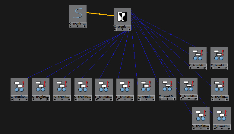
It meant spending a huge amount of time in the Hypershade, wiring up various items. It was extremely time consuming as I had to organise items in the hypershade so I could see what was parented to what and where the wires actually needed to go. Its definitely the largest wiring system I’ve created when rigging so far.


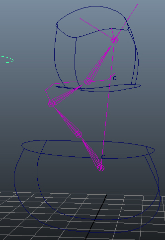
Having achieved the ability to blend between any of the different control systems, I needed to actually work out how to create a dynamic trunk. I watched a variety of tutorials and read a load of sites before deciding what I felt would be the cleanest, and simplest, way of rigging it. I applied another IK spline to the trunk and then duplicated the spline curve. This duplicate would be the input for my dynamics. So this was the curve that I had to create controls for. I made them in the same way as I did for the trunk, by creating clusters for the various points along the curve and parent constraining the clusters to controllers. I then applied dynamics to this duplicate curve which created another two curves in the process. One was the dynamic curve, and one was the output of the dynamics. The final step was to make this output curve control the original IK spline. I simply applied a blendshape to the spline, turned it up to 1 and locked the attribute so it couldn’t be changed or broken.
Working with dynamics is slightly strange though, as the dynamics only update when Maya plays the animation. This means you can tweak the starting position of the trunk, but it doesnt actually move the mesh (or the bones) until you press play. I think it unlikely the animators will want to ever just have a dynamic trunk, but I feel it may be nice to blend with some FK animation to add some extra secondary motion to the trunk.
Finally, I created some extra attributes so that the animators can edit the flexibility and stiffness of the dynamics and so affect the way Maya calculates the shape of the output curve.
All of the filming is now done and I have the footage from the first shoot, some of which is absolutely brilliant. This has got to be my favourite shot:

I just love the depth of field.
The second day of filming wasn’t nearly as cold as the first, and even with only two of us, we were done by lunch time. A huge chunk of our time was actually spent simply waiting for all the delivery vans to leave so that the streets were less cluttered. The final shot was probably one of the hardest to set up. I wanted to catch some footage of a flock of pidgeons being startled and flying away. In order to encourage them all to congregate in the first place, I scattered a small handful of bread crumbs across the pavement. It was a good 10-15 minutes before the first pidgeon found them, but once it did, the rest joined within a minute or two. Now all we had to do was scare them and manage to film them taking off. The first couple of attempts ended with me accidentally running in to shot, but after some practice I worked out where I had to stop. Sadly we couldnt move the camera fast enough to pan with them, so eventually we just settled on them flying out of shot.
It feels great to know that the stress of filming is hopefully over and all I now have to worry about is the digital side of things.
So, it finally happened. Yesterday was pretty intense and incredibly cold. Apparently one of the weather sites quoted Cardiff centre as being at about -6C (with windchill). It was absolutely bitter. I felt ever so bad for Rachel, Dylan and Hazel, and indescribably grateful that they had come to help despite the icy conditions.
We decided to get the biggest and most complicated shot out the way first, before Rachel, Dylan and Hazel arrived in Cardiff. Amy (my graduate compositor) and Jon (my 2nd year Motion Design cameraman) were an incredible help throughout the day. Helping me to judge camera angles for the best shots.


We spent some time setting up outside Cardiff Library before we finally got the green screen out and set to work. It was great fun, but since I managed to land the job of running from the elephant, it got tiring quite quickly. All too soon I needed to go and pick up Rachel and her kids from the station and I left the rest getting a few more takes of the elephant shot as well as some crowd shots and general reaction shots.
Once we got back I sent everyone but myself, Amy and Jon back to uni to warm up as Dylan was feeling shy and didn’t like such a large number of people. Dylan was an absolute natural. He rarely looked at the camera and he got almost every shot right first time. What a fantastic little star.
By lunch time we had got every shot we needed and I sent Rachel, Dylan and Hazel off to have some lunch and warm up whilst we got a few more shots with the monkey toy. In the end, Dylan didn’t want to take the monkey back home with him, so he now has pride of place on my desk.


After a stop in the union for lunch, we headed out to try and get some more shots. However it was getting a quite overcast and dark, even at half two, so I think it likely we will have to reshoot those. We finished the day with just two shots we hadn’t managed, and possibly an extra one if the afternoon ones turn out to be too dark.

Whenever we filmed something that would include the elephant, I made sure to take a set of photos of a chrome ball at various exposures. These will be used for the lighting in Maya. My chrome ball was a bit smaller than ones I have used in the past, and the camera’s zoom quite small, so I will have a bit of work in photoshop getting rid of myself and the camera in each shot.


